BETA SVU IO Link Alarms
Fanuc Beta I/O Link Alarms and Error Codes
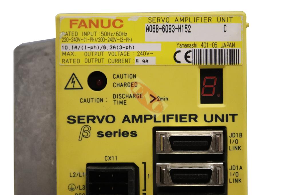
Fanuc Beta I/O Link Alarms. These alarm and error codes cover the A06B-6093-H15x/H17x series. Testing of FANUC BETA I/O Link Units. Please contact us if you need testing, a repair or an exchange part. For further information please visit our dedicated Fanuc Beta Servo Unit I/O Link Page. Program or Setting Alarms P/S
| Alarm Number | LED display | Description |
| 000 | U | A parameter that requires power down has been specified |
| 011 | F | The specified feedrate is zero |
| 013 | F | The specified feedrate ( max feedrate) is zero |
| 070 | t | More than 32 blocks have been registered for a buffering operation |
| 085 | h | Input from the reader/punch interface or the like caused an overrun, parity or framing error |
| 086 | h | Input from the reader/punch interface or the like includes an input/output unit operation ready signal (DR) that is set to off. |
| 087 | h | After input form the reader/punch interface or the like stops, character input does not stop even though ten characters have been input. |
| 090 | 9 | Reference position setting cannot be executed normally. |
| 093 | u | A first to third reference position return cannot be executed because the reference position has not yet been established. |
| 224 | u | The reference position has not yet been established. This occurs only when the ZRTN bit of parameter No.0001 is set to 0. |
| 250 | 7 | Input data 1 is invalid |
| 251 | 7 | Input data 2 in invalid |
| 255 | n | Operation cannot be activated because an invalid mode is specified or because block execution is in progress. |
| 290 | _ | The interface switch signal (DRC) was switched during block execution. |
| 291 | The speed of an axial movement specified by an external pulse has exceeded the upper limit. This occurs only when the EPEXA bit of parameter No.0001 is set to 1. | |
| 292 | A checksum error for the battery powered memory was detected. |
Pulse coder Alarms
| Alarm Number | LED display | Description |
| 300 | 5 | A communication error (DTER) for the serial pulse coder was detected. |
| 301 | 5 | A communication error (CRCER) for the serial pulse coder was detected. |
| 302 | 5 | A communication error (STBER) for the serial pulse coder was detected. |
| 303 | 6 | An LED disconnection (LDAL) was detected in the serial pulse coder. |
| 304 | 6 | A mispulse alarm (PMAL) for the serial pulse coder was detected. |
| 305 | 6 | A miscount alarm (CMAL) for the serial pulse coder was detected. |
| 306 | 3 | The motor was overheated (OHAL) |
| 308 | 6 | A soft phase alarm (SPHAL) was detected. |
| 319 | 11 | When the absolute pulse coder is used, the motor has not yet rotated through more than one turn after the first power up. |
| 350 | 2 | The battery voltage of the absolute pulse coder is low. |
| 351 | 1 | The battery voltage of the absolute pulse coder is low ( warning). |
| Alarm Number | LED display | Description |
| 400 | 4 | The servo motor has overheated (estimated value) |
| 401 | Servo amplifier ready signal (DRDY) went off. | |
| 403 | o | The cooling fans have overheated. |
| 404 | J | The regeneration discharge has over heated |
| 405 | n | Reference position return could not be executed correctly. |
| 410 | The servo position error in the stop state is larger than the value specified in parameter no 110. | |
| 411 | The servo position error during movement is larger than the value specified in parameter no 182. | |
| 412 | c | An overcurrent alarm is issued |
| 413 | y | A DC link overvoltage alarm is issued. |
| 414 | P | A DC link low voltage alarm is issued. |
| 417 | A | A parameter has been specified incorrectly. |
| 418 | E | A DO alarm is issued |
| 423 | t | The specified speed excess 32767000 detection units per second. |
| 425 | C | The cooling fan has stopped. |
Overtravel Alarms
| Alarm Number | LED display | Description |
| 500 | H | The positive stroke limit has been exceeded |
| 501 | H | The megative stroke limit has been exceeded |
| 510 | H | The positive soft stroke limit has been exceeded |
| 511 | H | The negative soft stroke limit has been exceeded |
System Alarms
| Alarm Number | LED display | Description |
| – | E | An error was detected in the RAM write/read test at power up. |
| – | 8 | An error was detected in the data collection check for the battery powered memory. |
| – | 9 | A data transfer alarm for the battery powered memory has been issued. |
| – | d | A watchdog was issued. |
| – | b | A checksum alarm for the control software ROM is issued. |
| – | 9 | A checksum alarm for the ROM that is built into the CPU is issued. |
| – | . | An error was detected in the control circuit. |
I/O Link Alarm
| Alarm Number | LED display | Description |
| – | L | A FANUC I/O link error occurred. A unit connected to the line was turned off |
No LED Display
| Alarm Number | LED display | Description |
| – | No indicators Lit | The control circuit is not operating normally |
DRIVES COVERED: